Updated 21 June 2025
My recently-acquired 2007 Moto Guzzi Breva 750 twin needed a tune-up, and to do it properly you really need a device to measure the vacuum on each throttle body. Some people use manometers, some use vacuum gauges, some buy a commercial balancer. I decided to make my own.
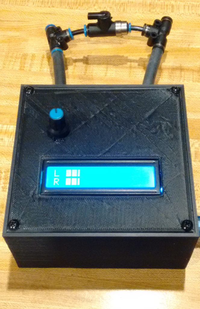
The photo above shows the completed unit. It is a 110mm square 3D-printed box and it contains an Arduino Uno processor to measure the vacuums and display them. The blue knob is a sensitivity control to smooth out the impulses from the engine.
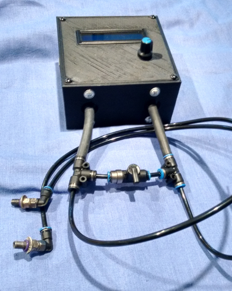
The back of the unit has the two pressure tappings from the sensors inside the box. They are connected to the hoses which screw into the 6mm holes in the throttle bodies. I made a cross-connector to enable me to check that the sensors themselves were balanced.
The inside of the box looks like this:
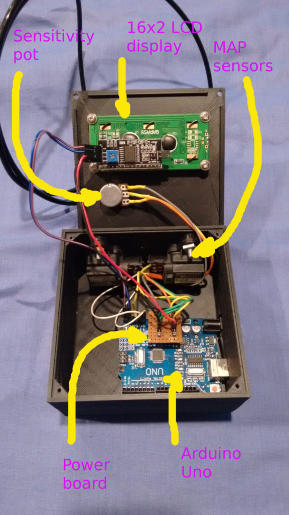
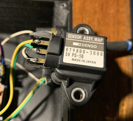
The vacuum sensors I used are Honda Civic MAP sensors. Why those ones? They were cheap on eBay (~AUD37 for the pair) ! I figure if they are sensitive enough to run a fuel injection system, then they must be OK for this job. They are powered with 5VDC and provide voltage outputs which I have connected to the analog inputs on the Uno.
To smooth out the engine pulses, you can use accumulators with flow controllers on the air flow, capacitor/resistor pairs on the electrical signal, or do what I have opted for – to do it in the program. The sensitivity potentiometer feeds another analog input on the Uno, and it adjusts the (single-exponential-smoothing-function) constant ALPHA. The smoothing works like this:
New-smoothed-value = new-value * ALPHA + old-smoothed-value * (1-ALPHA)
The display is a 2-line by 16 character unit with back-light and a I2C interface board piggy-backed on it. It provides a bar-graph representing the vacuum levels of each cylinder. The actual values of the vacuum are not important, it is only the relative values that you want, so I made the unit do auto-ranging – it adjusts the max and min values of the bar-graphs while the engine is running so that you can’t have the values off the scale.
The scan time when measuring the vacuum sensors is about 0.3msec, so I’ve put in a delay on each cycle to perform a measurement every 5msec. The time taken to update the display is about 80 msec, so that is only done every 40 scans. The setting up engine speed for my Guzzi is 3000rpm which equates to 20msec per rev and 40msec per 4-stroke-cycle, so the system will take about 8 measurements per 4-stroke cycle and update the display every 5 cycles, during which time it misses 2 cycles.
It took a little tweaking to initially get the configuration right, but it works well.
Now for some tech stuff:
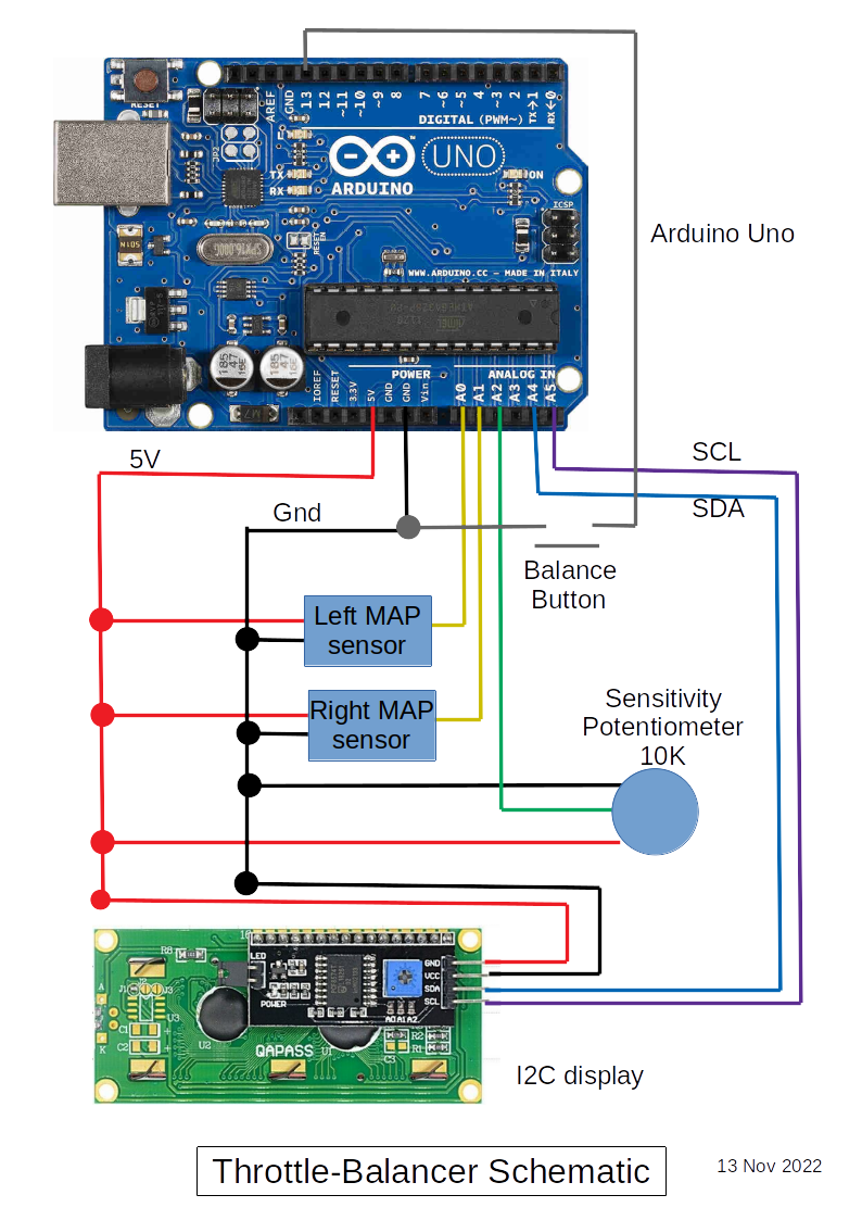
The schematic is shown above. The sensitivity pot doesn’t need to be 10K, you just need the voltage at the analog input to go from 5V to 0V. The standard control lines for I2C on the Uno are the analog inputs A4 and A5. As it happens I didn’t need to use them for anything else, so it wasn’t a problem.
There is a balance button that isn’t shown in the photos above, but is shown in the schematic. It is used to balance the two sides when the engine is not running. The initial values of the MAP sensors can differ from each other, so this button is pressed after power-up and before starting the engine.
The program is here. I don’t guarantee that I’ll maintain it as the latest version…
Updates
21 April 2020 – Original
21 May 2025 – Added MAP photo
21 June 2025 – Updated schematic with balance button