Updated 14 June 2025

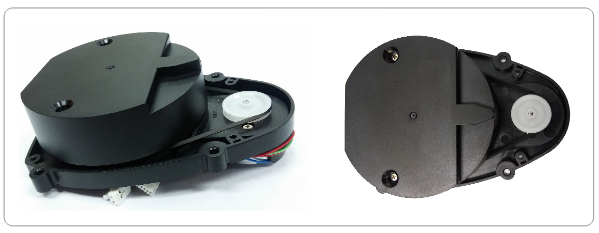
This is the Hitachi-LG HLS-LFCD2 2-dimensional LIDAR sensor. It is available cheaply on eBay. I wanted to run it using an NodeMCU ESP32-S processor and I ran into a few issues. Hopefully this helps others.
The datasheet for the sensor is here.
Connections:
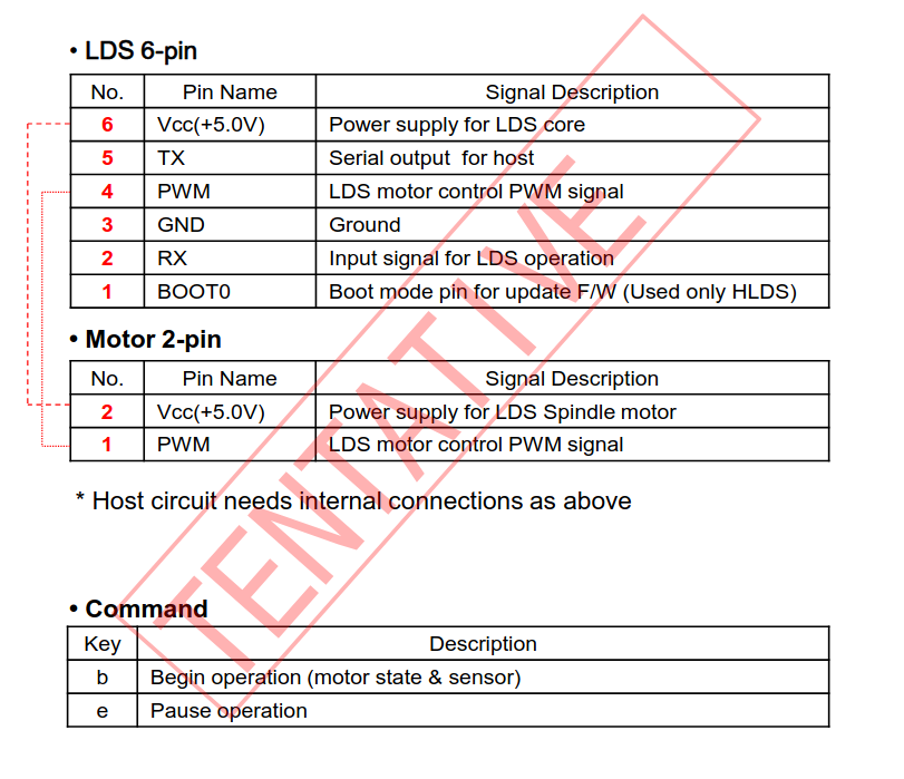
The connections shown below are from the datasheet above.

Points to note:
- There are two cable sets coming out of the unit. One is for the motor, and one set is for the LDS sensor controller. I cut the plugs off (after photographing them) and soldered the wires to the ESP32.
- You need to provide 5V to the processor and to the motor (both red wires, pins 6 and 2 above). They can be connected together.
- The on-board controller provides the PWM control for the motor speed. You don’t need to provide an output on the ESP32 to do that. Some other similar sensors need a PWM output from the host – this one doesn’t. Just connect the (orange, pin 4) PWM wire from the sensor controller to the (black, pin 1) PWM wire from the motor.
- Connect the (black, pin 3) GND wire to the ESP32 ground.
- The wire labelled TX (brown, pin 5) sends data from the sensor to the host (ESP32), so you need to connect that to the Rx pin on the host
- The wire labelled RX (green, pin 2) receives data from the host to turn the sensor on and off, so you need to connect that to the Tx pin on the host.
- The blue wire (pin 1) does nothing and doesn’t need to be connected.
- The host processor needs to be 3V3 serial, not 5V. The ESP32 is 3V3, so that’s OK. An Arduino Uno, for instance, is 5V, which isn’t OK.
Programming:
The serial connection is at 230400BAUD, 8N1.
The data will start to flow a couple of seconds after the sensor has been powered up. You can stop and start the sensor operation by sending “e” and “b” out the host Tx pin. I assume those commands are short for “end” and “begin”. If you want to send these codes from the Arduino IDE running on your desktop, you’ll have to put in some code to redirect the serial monitor input to the host’s serial output to the LIDAR.
The table in the datasheet shows the format of each data set. Every dataset needs checking. I found that around one in 15 datasets is faulty. I don’t know why, but you can filter them out easily.
The first thing to find in the data stream is the start flag. Each dataset starts with a “250” byte. So, you check each byte as it arrives, and when a 250 is received then that is the start of the next set.
The data is in a 42-byte set, including the start flag and the checksums. The last two bytes are checksums. The idea is you calculate the checksum for each set and compare it to the last two bytes. All three values should be the same. If not, discard the the dataset. Note that occasionally you will be missing the start flag. You need to allow for that in your programming.
The calculation is: Checksum = 255 – (sum of first 40 bytes) % 256
A new dataset is produced for each 6 degrees of rotation of the sensor, so there are 60 datasets per 360-degree revolution. The first data byte after the start flag contains the angle that the particular dataset refers to. The value of that byte actually starts at 160 (0xA0), not zero, so you need to subtract 160 to make sense of the angle. Contained within each dataset are six separate values of detected distance and intensity. These are for the angle in the first byte, plus values for the following five angles (one degree of rotation apart). These are referred to in the datasheet as “angle offsets”.
Example program below:
/*
This program runs a NodeMCU-32S connected to a Hitachi-LG HLS-LFCD2 2-dimensional LIDAR sensor

It collects the distance values in a data vector. The data is checked and, if OK,
then it adds the data to a data field array with one value for each 6 degrees of rotation.
The data is aggregated for each six-degree segment, and is smoothed

Note that in each data vector the sensor produces data for six 1-degree segments of rotation, but for this application that
level of accuracy is not needed

A check is kept on the number of good reads between bad reads and this is displayed on the monitor

*/


const uint8_t LIDAR_GPIO_RX = 16; // ESP32 GPIO pin connected to Lidar TX pin
const uint8_t LIDAR_GPIO_TX = 17; // ESP32 GPIO pin connected to Lidar RX pin


int SERIAL_BAUD = 230400;       // baud rate for both the serial monitor and LIDAR comms
int BYTECOUNT = 0;              // for counting the number of bytes in each dataset from the LIDAR
int DATAVECTOR[42];             // the dataset as sent from the LIDAR
int DATAFIELD[60];              // the storage array
const int TRIPVALUE = 1000;     // if objects are closer than this value in mm, then it shows as a visual "block" on the monitor
const float ALPHA = 0.80;       // for smoothing the distance values - % of new value
const float BETA = 0.01;        // for smoothing out the number of good reads before a bad one. Needs to be a low value
int GOODREADCOUNT = 0;          // the number of good reads between bad reads
float AVGGOODREAD = 10.0;       // the smoothed number of good reads
int DISPLAYTIME = 1000;         // milliseconds beween displays of data on the serial monitor

HardwareSerial LidarSerial(2);  // set up the ESP32 serial port to the LIDAR

void setup() {

  delay(3000);
  Serial.begin(SERIAL_BAUD);
  LidarSerial.begin(SERIAL_BAUD,SERIAL_8N1, LIDAR_GPIO_RX, LIDAR_GPIO_TX);
  Serial.println("Starting Lidar...");
  LidarSerial.print("b");  // start the sensor rotation
  for (int I = 0; I <60 ;I++){ DATAFIELD[I]= 5000;}  // populate the datafield with a high value
}

void PRINTDATAFIELD(){
  for (int I= 59; I >-1; I--){
    if (DATAFIELD[I] < TRIPVALUE){  // print the visual representation
      Serial.print("XXXX");
    } else {Serial.print("    ");}
    Serial.print(" ");
  }
  Serial.println("");
  for (int I= 59; I >-1; I--){      // print the index number
    Serial.printf("%04d",I);
    Serial.print(" ");
  }
  Serial.println("");
  for (int I= 59; I >-1; I--){     // print the distance value
    Serial.printf("%04d",DATAFIELD[I]);
    Serial.print(" ");
  }
  Serial.println("");
  Serial.print("Avg good reads: ");
  Serial.println(AVGGOODREAD);

}

void loop() {
  // Main code
  if (LidarSerial.available()){
    BYTECOUNT += 1;
    int READVALUE = LidarSerial.read();
    if (READVALUE == 250) {        // flag for new data vector
      int CHECKSUM = 0;
      for  (int I = 0; I < 40 ; I++) {CHECKSUM += DATAVECTOR[I];}
      CHECKSUM = 255 - (CHECKSUM % 256);
      if (CHECKSUM == DATAVECTOR[40] and CHECKSUM == DATAVECTOR[41]){ // good read
        GOODREADCOUNT += 1;
        int INDEX = DATAVECTOR[1]-160 ;  // the data field 0 to 60  (360 degrees of rotation)
        int NEWVALUE = 0;
        if (INDEX >= 0 and INDEX < 60){  // check that the index value is valid
          for (int I = 0; I < 6; I++){
          NEWVALUE += (DATAVECTOR[6 + I * 6] + DATAVECTOR[7 + I * 6]*256);  // add up all the angle offset values
          }
          if (NEWVALUE > 300 ) {  // not interested in distances less than this
            DATAFIELD[INDEX] = DATAFIELD[INDEX] * (1.0-ALPHA) + NEWVALUE/6 * ALPHA; //  smooth the averaged data
          }
        }

      }
      else {
        AVGGOODREAD = AVGGOODREAD * (1.0-BETA) + (float)GOODREADCOUNT * BETA;  // smoothing
        GOODREADCOUNT = 0;
      }

      BYTECOUNT =  0;
    }
    if (BYTECOUNT < 42){ // save data to data vector
      DATAVECTOR[BYTECOUNT] = READVALUE;
    }
    }
  if (Serial.available() > 0) {LidarSerial.write(Serial.read());}  // transfer any commands from Serial Monitor

  if (millis() % DISPLAYTIME == 0){PRINTDATAFIELD();  }    // print the data field on the serial monitor


}