Using a Raspberry-Pi to extract information from a Honda CTX-700 ECU.
Updated November 2019
This project was completed in Feb 2016 and was operational until I sold the bike in Nov 2019. The system is no longer in operation.
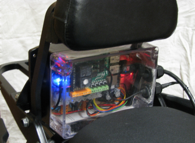
Here is the Raspberry-Pi mounted on the bike:
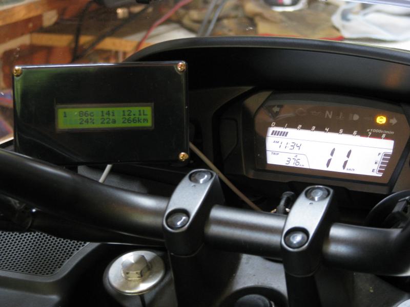
The data is shown on a character display on the dash. It contains the following information:
Top row: gear position, coolant temp, instantaneous fuel economy (km/litre), fuel in tank
Bottom row: % of chain oiler cycle time, average fuel economy, km to empty.
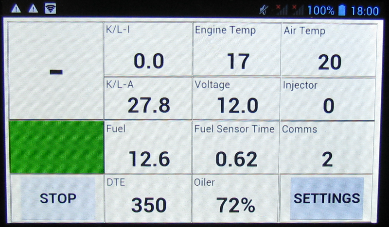
There is a detailed web interface that can be accessed via a smartphone:
This document was written to help others to build a system to communicate with the ECU on Honda motorcycles. The vast majority of information here has been obtained from contributors on the pgmfi.org forum. That forum has been “down” for months, so the information is not accessible. Hence this document. Note: Feb 2016 – pgmfi.org is back up!
The key steps to extract information from the ECU are:
-
- Make a cable to connect to the ECU diagnostics socket
-
- Make an interface board to isolate the 12V bike signals from the 5V computer comms
-
- Set up serial communications at 10400baud. This is a non-standard baud rate, so you can’t use a normal USB to serial adapter, and you can’t use a standard automotive ELM327-based unit because the ELM unit calculates the checksum differently and adds it automatically whether you want it to or not.
-
- Use the correct message protocol. Honda does not use the standard ISO-9141-2 protocol.
-
- Use the correct initialisation sequence. Honda does not use the standard ISO initialisation sequence (another reason not to use an ELM unit)
-
- Determine where the data you are looking for is located in the ECU memory. There are a few standard locations, but you may have to proceed to step 7 to test other locations if the standard ones don’t work.
-
- Write a program for your computer/Arduino/whatever to get the data and do with it what you will.
- Package it all into something that fits on your bike.
My setup was based on a Raspberry-Pi model B+ with a PiFace2 I/O board running Raspian. I used a PiFace board because I wanted I/O for driving various things on the bike eg: an auto chain oiler. However, I also used it for pulling the K-line low (see section 5 below). You could use some other method for this function, but it was convenient for me to use one of the PiFace’s relays.
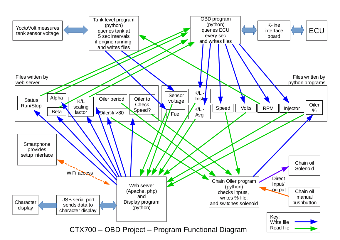
The information flows in my system are quite complex:
Going through these items one by one:
1. Make a cable
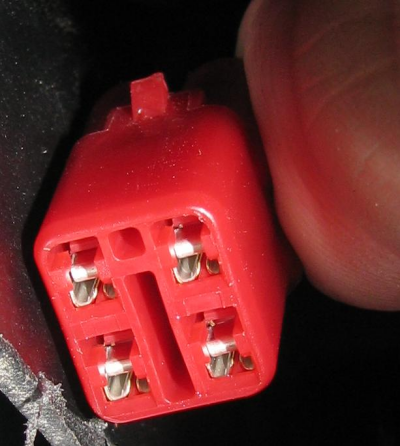
You need to locate the socket on your bike. The CTX socket is a red 4-pin unit near the battery. The connections are 12V, earth, bi-directional K-line and a reset line. You need only the first three to talk to the ECU. Check your manual for the wire colours. The CTX uses a Sumitomo HM090 connector. The connector on the bike looks like this:
2. Make an Interface Board
I made the following board:

The K-line rides high (12V) at rest.
I used the above design incorporating optocouplers so that the bike12V was completely isolated from the computer serial adapter. It is possible to use other transistor-based circuits, but you don’t get the same level of isolation.
3. Set up Serial Comms
I used a FT232RL USB to serial converter, because it has a base frequency which is able to be scaled down to the 10400baud needed. When plugged into the USB port on the Rpi, it comes up as /dev/ttyUSB0.
To configure the port for 10400baud:
| #!/bin/bash setserial -v /dev/ttyUSB0 spd_cust divisor 2307 |
This sets the port so that, when you use a program (eg Python) to specify 38400baud for the port, it goes to the custom speed instead of 38400. The port settings are 8 bits, no parity, one stop bit.
To get the adapter to work properly on a R-Pi, you need to add the following in the /boot/cmdline.txt file :
dwc_otg.speed=1
4. Use the Correct Message Protocol
Basically the ECU simply responds to requests for information. It doesn’t care if the response is not heard.
A typical request is of the form:
72 07 72 11 00 14 F0 (in hexadecimal)
72: the destination code (I think?)
07: the number of characters in the message including the checksum
72: the type of query (“give me data from memory?”)
11: the data table number
00: the starting register within data table 11
14: the finishing register within data table 11
F0: the checksum
The ECU will respond with a similar format:
02 1A 72 11 00 XX XX XX …XX YY
02: the destination code (I think?)
1A: the number of characters in the message (in this case 26 decimal)
72: the type of query (“data from memory?”)
11: the data table number
00: the starting register
XX: the data
YY: the checksum
The checksum is calculated differently to the ISO OBDII protocol. It goes like this:
Sum all the values of the characters together, and take that value from 100 (hex). If the sum is greater than 100 hex, just use the last two characters (in hex).
So, the request message above (in hex) would be:
0x72 + 0x07 + 0x72 + 0x11 + 0x00 + 0x14 = 0x110
Use only the last two characters, 0x10
0x100 – 0x10 = 0xF0 = the checksum F0
The response checksum is calculated similarly.
There are other query types (the third character in the request sequence). The ones I know to exist are 71, 72, 73 and 74. Code 71 requests all of the table data, rather than a subset:
72 05 71 00 18 requests all of the data in table 00
I don’t know what a code 73 or 74 request does.
5. Use the correct Initialisation Sequence
The ECU will not respond until it has received the correct initialisation sequence. I used this:
-
- Pull the K-line low for 70msec
-
- Return the K-line to the high state for 120msec
-
- Send “Wakeup” message: FE 04 FF FF. No response is expected
-
- Wait 200msec
-
- Send “Initialise” message: 72 05 00 F0 99
-
- The ECU should respond with: 02 04 00 FA
That’s it. You can then send requests and the ECU should respond with the data requested. The communications needs to be “kept alive”, however. That means that if the ECU hasn’t received a request within a certain time it goes back to sleep and needs to be initialised again. I think the time is around 3 sec.
Note that I haven’t tested the above times to see what the limits are. All I know is that they work for me and my system.
How do you pull the K-line low? I used a relay driven by the R-Pi. It simply shorted the K-line and ground terminals on the interface board. It doesn’t have to be a relay. If you’re using a “soft serial” where you can directly control the Tx line, you can simply pull that low, and the interface board will pull the K-line low.
6. Determine where the data is located
I tabulated the information obtained from a few guys working on this project at pgmfi.org . The data for the small selection of bikes shows that the critical information is held in only a few data table, and some of these tables are duplicated (don’t know why). The most frequently used tables are 00, 10 and 60, 11 and 61, so those the re best places to start. Refer to the “Honda Data Tables.pdf” document:
The document shows the contents of the various tables on the bikes tested, and it shows how to calculate the real life data from the values that come from the ECU. The data comes in single or double bytes – double bytes are used for data that needs more precision or has a high value (eg: engine speed)
If these data tables don’t work for you, you’ll have to write a program to “scan” through the various table numbers to see where the data exists. The ECU will simply reflect your query back at you if the table doesn’t exist.
7. Write a program
Writing a program is up to you. I used Python running under Raspbian. You need a program that handles serial comms (obviously). You will have to be able to handle the following:
-
- Initialisation
-
- sending/receiving data normally
-
- determining if the received data is valid (checksum)
-
- handling comms errors (the bike is an electrically noisy place)
-
- keeping the ECU awake, and waking it if it goes to sleep
Receiving data is tricky. Because all the comms come on one line, the serial adapter receives all the data it sends, as well as the responses from the ECU. In addition, the ECU doesn’t necessarily respond immediately – it may be busy doing something else, so you have to wait until you have received the full response. In addition, the program has to ignore anything that comes back from the initialisation sequence.
I used the following process:
-
- clear send buffer
-
- send message
-
- clear receive buffer
-
- loop through a single character receive program until a response of the required length has been received (I know how long the response should be)
-
- if no new characters are received within x cycles, exit the loop
-
- determine if the message is valid – if not, don’t process, and try sending again. If a valid message is not received in x tries, reinitialise the comms.
-
- process the valid response
8. Package it
This is what I did – it may give you ideas. The R-Pi controls the following:
-
- The OBD communication
-
- The auto chain oiler solenoid
-
- The fuel tank level reporting
-
- The web server which provides the user interface
My R-Pi was set up as a wireless hotspot so the user interface (an old Medion smartphone) could be used without wires. In addition, it means that any program changes can be done without connecting a keyboard and monitor to the computer.
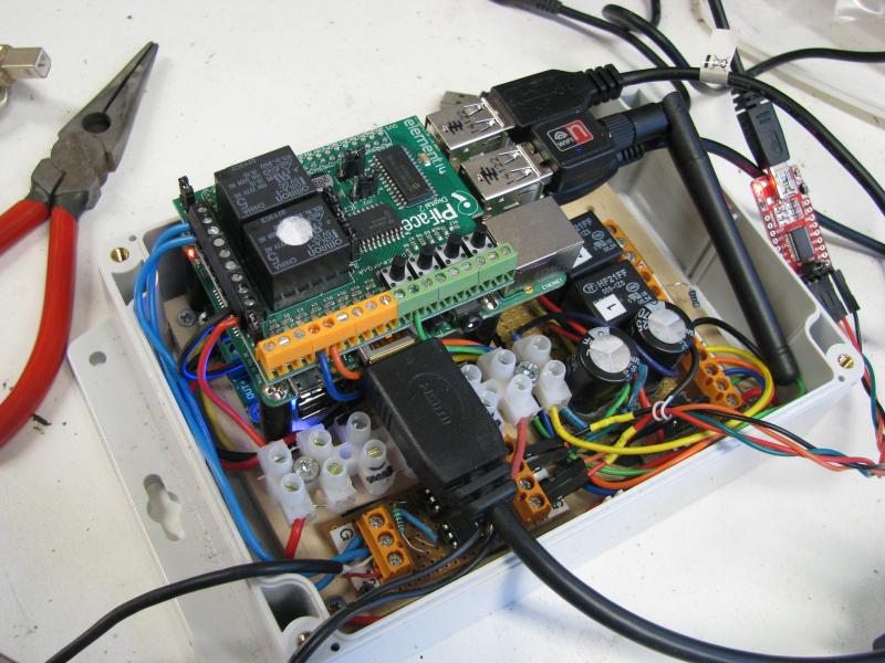
Here’s the assembly on the test bench:
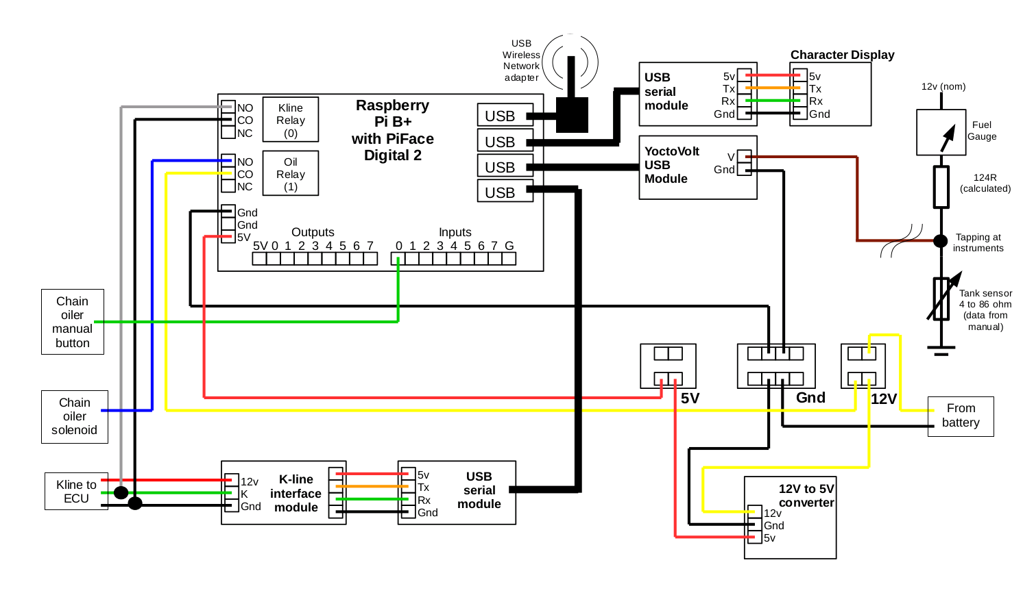
Here’s the wiring diagram: